FPGA開発日記

カテゴリ別記事インデックス https://msyksphinz.github.io/github_pages , English Version https://fpgadevdiary.hatenadiary.com/

Googleの量子コンピュータフレームワークCirqを使ってみる(5. 資料を見ながらCirqの計算フローを追ってみる)

Cirqの計算プロセスの続きである。Cirqがどのようにして量子状態の計算を行っているのかを見ていく。

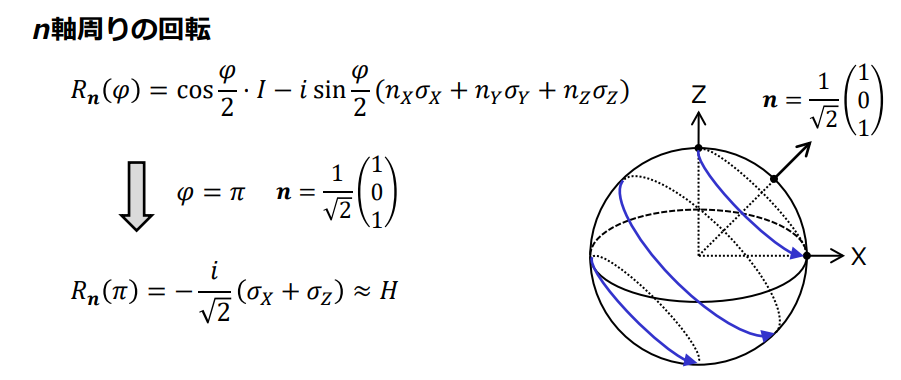
とりあえず、前回から少しコードを変えた。アダマールゲートを使用するように変更する。アダマールゲートというのは、量子を重ね合わせの状態に持っていくゲートのことで、具体的には以下のような行列を計算する。1

$$H=\dfrac{1}{\sqrt{2}}\begin{pmatrix} 1 & 1\\ 1 & -1 \end{pmatrix}$$

ただし、これはもう少し一般化できて、XZ軸の周りで回転させるときは下記のように表される(以下は https://www.appi.keio.ac.jp/Itoh_group/abe/pdf/ap2016_4.pdf より抜粋)。
f:id:msyksphinz:20181001011942p:plain
図. 一般的なアダマールゲートの表現(https://www.appi.keio.ac.jp/Itoh_group/abe/pdf/ap2016_4.pdf より抜粋)

さて、下記のようにCirqで記述した量子回路はどのようにして計算されるのだろうか。

import cirq

qbits = [cirq.GridQubit(0, i) for i in range(1)]

circuit = cirq.Circuit()
circuit.append(cirq.H.on(qbits[0]))

simulator = cirq.google.XmonSimulator()

results = simulator.run(circuit, repetitions=1000, qubit_order=qbits)

まずは回路の構成をprintを入れて見ていくと、以下のようになった。ExpWGateExpZGateというもので構成されているようだ。そんな気がする。

(Pdb) c
> /home/msyksphinz/work/Cirq/cirq/google/sim/xmon_simulator.py(535)_simulator_iterator()
-> if isinstance(gate, xmon_gates.ExpZGate):
(Pdb) p circuit
cirq.Circuit(moments=[
    cirq.Moment(operations=[
        ExpWGate(half_turns=-0.5, axis_half_turns=0.5).on(cirq.GridQubit(0, 0)),
    ]),
    cirq.Moment(operations=[
        ExpZGate(half_turns=1.0).on(cirq.GridQubit(0, 0)),
    ]),
])

PDBなどでPythonのコードを追いかけていくと、実際のシミュレーションはcirq/google/sim/xmon_stepper.pyで実装されている。 ゲートを適用しているのは、以下のコードのようだ。

  • cirq/google/sim/xmon_stepper.py
class ThreadlessPool(object):
    """A Pool that does not use any processes or threads.

    Only supports map, close, and join, the later two being trivial.
    No enforcement of closing or joining is done, so map can be called
    repeatedly.
    """

    # noinspection PyMethodMayBeStatic
    def map(self, func, iterable, chunksize=None):
        assert chunksize is None, 'Chunking not supported by SimplePool'
        return [func(x) for x in iterable]

それぞれfuncにはどのようなものが入っているのかを調査すると、以下のようになった。

func(x) = <function _w_within_shard at 0x7fbbbe0a62f0>
func(x) = <function _norm_squared at 0x7fbbbe0a6510>
func(x) = <function _renorm at 0x7fbbbe0a6598>
func(x) = <function _clear_scratch at 0x7fbbbe0a6048>
func(x) = <function _apply_scratch_as_phase at 0x7fbbbe0a6268>
func(x) = <function _clear_scratch at 0x7fbbbe0a6048>
func(x) = <function _single_qubit_accumulate_into_scratch at 0x7fbbbe0a60d0>
func(x) = <function _apply_scratch_as_phase at 0x7fbbbe0a6268>
func(x) = <function _clear_scratch at 0x7fbbbe0a6048>
func(x) = <function _apply_scratch_as_phase at 0x7fbbbe0a6268>
func(x) = <function _state_shard at 0x7fbbbe0a4c80>

例えば、Hゲートを実行しているのは_w_within_shardのような気がする。

  • `cirq/google/sim/xmon_stepper.py``
def _w_within_shard(args: Dict[str, Any]):
    """Applies a W gate when the gate acts only within a shard."""
    index = args['index']
    half_turns = args['half_turns']
    axis_half_turns = args['axis_half_turns']
    state = _state_shard(args)
    pm_vect = _pm_vects(args)[index]
    num_shard_qubits = args['num_shard_qubits']
    shard_size = 2 ** num_shard_qubits

    reshape_tuple = (2 ** (num_shard_qubits - 1 - index), 2, 2 ** index)
    perm_state = np.reshape(
        np.reshape(state, reshape_tuple)[:, ::-1, :], shard_size)
    cos = np.cos(-0.5 * np.pi * half_turns)
    sin = np.sin(-0.5 * np.pi * half_turns)

    cos_axis = np.cos(np.pi * axis_half_turns)
    sin_axis = np.sin(np.pi * axis_half_turns)

    new_state = cos * state + 1j * sin * perm_state * (
        cos_axis - 1j * sin_axis * pm_vect)
    np.copyto(state, new_state)

各種関数にprintを挟んで実行してくと、以下のようになった。

func(x) = <function _w_within_shard at 0x7fbbbe0a62f0>
<perm_state = [0.+0.j 1.+0.j], pm_state = [ 1 -1]
<              cos_axis - 1j * sin_axis * pm_vect  = [6.123234e-17-1.j 6.123234e-17+1.j]>
<perm_state * (cos_axis - 1j * sin_axis * pm_vect) = [0.000000e+00+0.j 6.123234e-17+1.j]>
half_turns = -0.5, state = [1.+0.j 0.+0.j], new_state = [ 0.70710677+0.00000000e+00j -0.70710677+4.32978021e-17j]
func(x) = <function _norm_squared at 0x7fbbbe0a6510>
func(x) = <function _renorm at 0x7fbbbe0a6598>
state = [ 0.70710677+0.0000000e+00j -0.70710677+4.3297803e-17j]
new_state = [ 0.7071068+0.000000e+00j -0.7071068+4.329781e-17j]
func(x) = <function _clear_scratch at 0x7fbbbe0a6048>
func(x) = <function _apply_scratch_as_phase at 0x7fbbbe0a6268>
state = [ 0.7071068+0.000000e+00j -0.7071068+4.329781e-17j], _scratch_shard(args) = [0.+0.j 0.+0.j]
new_state = [ 0.7071068+0.000000e+00j -0.7071068+4.329781e-17j]
func(x) = <function _clear_scratch at 0x7fbbbe0a6048>
func(x) = <function _single_qubit_accumulate_into_scratch at 0x7fbbbe0a60d0>
func(x) = <function _apply_scratch_as_phase at 0x7fbbbe0a6268>
state = [ 0.7071068+0.000000e+00j -0.7071068+4.329781e-17j], _scratch_shard(args) = [-1.+0.j  1.+0.j]
new_state = [-3.090862e-08-0.7071068j  3.090862e-08-0.7071068j]
func(x) = <function _clear_scratch at 0x7fbbbe0a6048>
func(x) = <function _apply_scratch_as_phase at 0x7fbbbe0a6268>
state = [-3.090862e-08-0.7071068j  3.090862e-08-0.7071068j], _scratch_shard(args) = [0.+0.j 0.+0.j]
new_state = [-3.090862e-08-0.7071068j  3.090862e-08-0.7071068j]
func(x) = <function _state_shard at 0x7fbbbe0a4c80>
Counter({1: 502, 0: 498})

最初のアダマールゲートの適用で、[1.+0.j 0.+0.j][ 0.70710677+0.00000000e+00j -0.70710677+4.32978021e-17j] に変換されていることが分かる。 そのあとで_apply_scratch_as_phaseにより[ 0.7071068+0.000000e+00j -0.7071068+4.329781e-17j] から [-3.090862e-08-0.7071068j 3.090862e-08-0.7071068j] になっているが良く分からない。

つまりこのあたりを見ていけばCirqの量子計算の核の部分を見ることができそうだ。

ちなみに、Cirqはやはり量子ビットの数を大きくするとその 2^{n}の行列を用意するようだ。 17ビットを超えるとそれ以上は_within_shardは呼ばれなくなった。

perm_state = [0.+0.j 1.+0.j]
pm_vect    = [ 1 -1]
state      = [1.+0.j 0.+0.j]
new_state  = [ 0.70710677+0.00000000e+00j -0.70710677+4.32978021e-17j]
perm_state = [0.+0.j 0.+0.j 1.+0.j 0.+0.j]
pm_vect    = [ 1  1 -1 -1]
state      = [1.+0.j 0.+0.j 0.+0.j 0.+0.j]
new_state  = [ 0.70710677+0.00000000e+00j  0.        +0.00000000e+00j
 -0.70710677+4.32978021e-17j  0.        +0.00000000e+00j]
perm_state = [0.+0.j 0.+0.j 0.+0.j 0.+0.j 0.+0.j 0.+0.j 0.+0.j 0.+0.j 0.+0.j 0.+0.j
 0.+0.j 0.+0.j 0.+0.j 0.+0.j 0.+0.j 0.+0.j 1.+0.j 0.+0.j 0.+0.j 0.+0.j
 0.+0.j 0.+0.j 0.+0.j 0.+0.j 0.+0.j 0.+0.j 0.+0.j 0.+0.j 0.+0.j 0.+0.j
 0.+0.j 0.+0.j]
pm_vect    = [ 1  1  1  1  1  1  1  1  1  1  1  1  1  1  1  1 -1 -1 -1 -1 -1 -1 -1 -1
 -1 -1 -1 -1 -1 -1 -1 -1]
state      = [1.+0.j 0.+0.j 0.+0.j 0.+0.j 0.+0.j 0.+0.j 0.+0.j 0.+0.j 0.+0.j 0.+0.j
 0.+0.j 0.+0.j 0.+0.j 0.+0.j 0.+0.j 0.+0.j 0.+0.j 0.+0.j 0.+0.j 0.+0.j
 0.+0.j 0.+0.j 0.+0.j 0.+0.j 0.+0.j 0.+0.j 0.+0.j 0.+0.j 0.+0.j 0.+0.j
 0.+0.j 0.+0.j]
new_state  = [ 0.70710677+0.00000000e+00j  0.        +0.00000000e+00j
  0.        +0.00000000e+00j  0.        +0.00000000e+00j
  0.        +0.00000000e+00j  0.        +0.00000000e+00j
  0.        +0.00000000e+00j  0.        +0.00000000e+00j
  0.        +0.00000000e+00j  0.        +0.00000000e+00j
  0.        +0.00000000e+00j  0.        +0.00000000e+00j
  0.        +0.00000000e+00j  0.        +0.00000000e+00j
  0.        +0.00000000e+00j  0.        +0.00000000e+00j
 -0.70710677+4.32978021e-17j  0.        +0.00000000e+00j
  0.        +0.00000000e+00j  0.        +0.00000000e+00j
  0.        +0.00000000e+00j  0.        +0.00000000e+00j
  0.        +0.00000000e+00j  0.        +0.00000000e+00j
  0.        +0.00000000e+00j  0.        +0.00000000e+00j
  0.        +0.00000000e+00j  0.        +0.00000000e+00j
  0.        +0.00000000e+00j  0.        +0.00000000e+00j
  0.        +0.00000000e+00j  0.        +0.00000000e+00j]

ただし量子ビットを18ビットよりも大きくすると_w_within_shardは呼ばれなくなった。 別のアルゴリズムを使っているのだろうか。
Googleの量子コンピュータフレームワークCirqを使ってみる(4. Cirqの中身を追ってみる)

Google量子コンピュータフレームワークであるCirqを使っており、簡単な回路なら記述できるようになった。

次に疑問点として沸いてくるのは、Cirqはどのようにして量子状態のシミュレーションを行っているのかというところだ。 Pythonのコードを見るのは苦手だけれども、どうにかしてこれを追ってみることにした。

Pythonパッケージを変更して試行してい見る。

まずはCirqでシミュレーションを実行するにあたり以下の簡単な量子回路を用意した。 非常に簡単な回路だ。Xゲートを量子ビットに適用しているだけである。

  • cnot_test.py
import cirq

qbits = [cirq.GridQubit(0, i) for i in range(1)]

circuit = cirq.Circuit()
circuit.append(cirq.X.on(qbits[0]))

simulator = cirq.google.XmonSimulator()
circuit.append(cirq.measure(qbits[0], key='c'))

results = simulator.run(circuit, repetitions=1, qubit_order=qbits)
print (results.histogram(key='c'))

量子回路は以下のようになる。

(0, 0): ───X───M('c')───

いちいちパッケージをビルドしてインストールするのは面倒なので良い方法はないかと悩んでいたのだが、Twitterpython setup.py developでリンクを張られた状態でパッケージを使用できることが分かった。これは便利。

python setup.py develop

シミュレーションの様子を追いかけてみる

まずはcircuit.X.on()circuit.CNOT.on()がどこで実行されているのかを確認する。これはどうもXを実行するためのゲートオブジェクトを返しているだけのようだ。

  • cirq/ops/common_gates.py
CNOT = CNotGate()  # Controlled Not Gate.
  • cirq/ops/common_gates.py
class CNotGate(eigen_gate.EigenGate,
               gate_features.TextDiagrammable,
               gate_features.CompositeGate,
               gate_features.TwoQubitGate,
               gate_features.QasmConvertibleGate):
...
    def on(self, *args: raw_types.QubitId,
           **kwargs: raw_types.QubitId) -> gate_operation.GateOperation:
        if not kwargs:
            return super().on(*args)
        if not args and set(kwargs.keys()) == {'control', 'target'}:
            return super().on(kwargs['control'], kwargs['target'])
        raise ValueError(
            "Expected two positional argument or else 'target' AND 'control' "
            "keyword arguments. But got args={!r}, kwargs={!r}.".format(
                args, kwargs))
  • cirq/ops/raw_types.py
class Gate:
...
    def on(self, *qubits: QubitId) -> 'gate_operation.GateOperation':
        """Returns an application of this gate to the given qubits.

        Args:
            *qubits: The collection of qubits to potentially apply the gate to.
        """
        # Avoids circular import.
        from cirq.ops import gate_operation

        if len(qubits) == 0:
            raise ValueError(
                "Applied a gate to an empty set of qubits. Gate: {}".format(
                    repr(self)))
        self.validate_args(qubits)
        return gate_operation.GateOperation(self, list(qubits))
  • cirq/ops/gate_operation.py
class GateOperation(raw_types.Operation,
                    extension.PotentialImplementation[Union[
                        gate_features.BoundedEffect,
                        gate_features.CompositeOperation,
                        gate_features.ExtrapolatableEffect,
                        gate_features.ParameterizableEffect,
                        gate_features.PhaseableEffect,
                        gate_features.ReversibleEffect,
                        gate_features.TextDiagrammable,
                        gate_features.QasmConvertibleOperation,
                    ]]):
    """An application of a gate to a collection of qubits.

    Attributes:
        gate: The applied gate.
        qubits: A sequence of the qubits on which the gate is applied.
    """

    def __init__(self,
                 gate: raw_types.Gate,
                 qubits: Sequence[raw_types.QubitId]) -> None:
        self._gate = gate
        self._qubits = tuple(qubits)

次に、量子ビットを計測したときにどのように実行されるのかを観測した。

  • cirq/google/sim/xmon_stepper.py
class Stepper(object):
...
    def sample_measurements(
            self,
            indices: List[int],
            repetitions: int=1) -> List[List[bool]]:
...
        # Calculate probabilities and reshape to tensor of qubits.
        tensor = np.reshape(np.abs(self.current_state) ** 2,
                            self._num_qubits * [2])

        # Tensor axis order is reverse of index order, so we transpose here.
        tensor = np.transpose(tensor)

このtensorという変数が怪しい気がする。いろいろ量子回路を変えながらtensorの値を出力してみた。

まずはXゲート→CNOTゲートを当てたもの。

circuit = cirq.Circuit()
circuit.append(cirq.X.on(qbits[0]))
circuit.append(cirq.CNOT.on(qbits[0], qbits[1]))

[cirq.GridQubit(0, 0), cirq.GridQubit(0, 1)]
(0, 0): ───X───@───
               │
(0, 1): ───────X───

current_state = [ 2.0323548e-18-8.4182900e-19j  1.1845434e-17+2.8597407e-17j
 -2.2809713e-08+5.5067517e-08j  1.0000001e+00+0.0000000e+00j]

tensor = [[4.8391427e-36 9.5812607e-34]
 [3.5527145e-15 1.0000002e+00]]
Counter({1: 1})

次にCNOTゲートのみ当てたもの。

circuit = cirq.Circuit()
circuit.append(cirq.CNOT.on(qbits[0], qbits[1]))

current_state = [-2.9802322e-08+1.0000000e+00j -5.7024274e-09-1.3766877e-08j
 -2.8597404e-17-1.1845433e-17j -8.4182890e-19+2.0323546e-18j]

[cirq.GridQubit(0, 0), cirq.GridQubit(0, 1)]
(0, 0): ───@───
           │
(0, 1): ───X───
tensor = [[1.000000e+00 2.220446e-16]
 [9.581259e-34 4.839141e-36]]
Counter({0: 1})

やはりtensorの値が変わったので、この変数が量子ビットの状態を保持していそうな気がする。

ただし具体的にどうやって量子ゲートの計算をしているのかについてはたどり着かなかった。 もう少し掘り下げてみていきたい。

f:id:msyksphinz:20180923015903p:plain

ゼロから作る量子コンピュータ・シミュレータ(5. Pythonインタフェースから全加算器を構成してシミュレート)

フルスクラッチ量子コンピュータ・シミュレータを作る話、骨格となる部分はおおよそ完成し、量子ビットを取り扱う方法を考える。

量子ビットを作成する方法の検討

量子ビットは、1量子ビットPythonの1変数として宣言できるようにしたい。 例えば、以下のようにPythonで記述すると2つの量子ビットが個別に宣言される。

qbit1 = qbit()
qbit2 = qbit()

で、この状態だと2量子ビット存在するので、状態ベクトルとしては 2^{2}のベクトルを内部に保持する必要がある。 さらに量子ビットを追加するとベクトル長は8にまで拡大するので、そのたびに状態ベクトルを拡大する必要がある。

いろいろ考えて、とりあえず今はグローバルに量子ビットを管理するクラスを1つだけ用意し、量子ビットが追加される毎に状態ベクトルを再定義することにした。 そして、量子ビットそのものを示す変数(上記だとqbit1, qbit2)は単なる整数として表現することにした。

PyMethodDef qbit_methods[] = {
...
  { "make_qbit" , (PyCFunction)MakeQbits, METH_VARARGS, "Make Qbits"                     },
...
PyObject* MakeQbits (PyObject* self, PyObject* args)
{
  int new_qbit_idx = g_qbits.AddQbit();
  PyObject *ret = Py_BuildValue("I", new_qbit_idx);
  return ret;
}

量子ビットの操作

例えば、2つの量子ビットに対してCNOTゲートを適用する場合、以下のように記述するイメージだ。

cnot(qbit1, qbit2)

結局のところはqbit1, qbit2は整数で割り当てられたインデックスなので、インデックスに基づいて内部で量子状態を変えているに過ぎない。

PyMethodDef qbit_methods[] = {
...
  { "cnot"      , (PyCFunction)CNot     , METH_VARARGS, "Get Applied CNot"               },
...
PyObject* CNot (PyObject* self, PyObject* args)
{
  int a_idx, b_idx;
  if (!PyArg_ParseTuple(args, "ii", &a_idx, &b_idx))
    return NULL;
  g_qbits.CNot (a_idx, b_idx);

  return Py_BuildValue("i", 0);
}

g_qbits.CNot (a_idx, b_idx)は、行列ベクトルの操作する対象の量子ビット2つ(結局はインデックス)指定して量子状態を変える操作を実行する。

Pythonインタフェースを使って全加算器を作る

という訳で、Pythonインタフェースを整備したので、これを使って全加算器を作る。

量子ビットとしては、入力ビットとしてqbit_a, qbit_b 答えとしてqbit_c0, qbit_c1を用意した。

  • test/test_fulladder.py
qbit_a  = qbit.make_qbit()
qbit_b  = qbit.make_qbit()
qbit_c0 = qbit.make_qbit()
qbit_c1 = qbit.make_qbit()

for b in range (2):
    for a in range (2):
        if a != qbit.val(qbit_a):
            qbit.x(qbit_a)
        if b != qbit.val(qbit_b):
            qbit.x(qbit_b)

        if qbit.val(qbit_c0) == 1:
            qbit.x(qbit_c0)

        print('a + b = s1,s0 => %d + %d = ' % (qbit.val(qbit_a), qbit.val(qbit_b)), end="")

        qbit.ccnot(qbit_a, qbit_b, qbit_c1);
        qbit.cnot (qbit_a, qbit_b);
        qbit.ccnot(qbit_b, qbit_c0, qbit_c1);
        qbit.cnot (qbit_b, qbit_c0);

        print('%d,%d' % (qbit.val(qbit_c1), qbit.val(qbit_c0)))

実際に全加算器を実行しているのは、後半のccnotから始まる4行に過ぎないのだが、それ以外のところでは量子ビットの初期化を行っている。

a=0, b=0 ... a=1, b=1の順番に4種類の加算を実行しているのだが、その度に量子の状態を初期化している。

さっそく実行してみた。正しく計算できている。問題なさそうだ。

$ ./qbit_simulator ../test/test_fulladder.py
a + b = s1,s0 => 0 + 0 = 0,0
a + b = s1,s0 => 1 + 0 = 0,1
a + b = s1,s0 => 0 + 1 = 0,1
a + b = s1,s0 => 1 + 1 = 1,0
f:id:msyksphinz:20180927230554p:plain

ゼロから作る量子コンピュータ・シミュレータ(4. シミュレータにPythonのインタフェースを追加する)

フルスクラッチ量子コンピュータ・シミュレータを作る話、骨格となる部分はおおよそ完成してきたので次はインタフェースの部分を調整する。

現在は量子回路を生成する部分はC++で記述しており、量子回路を書き換えるたびにリコンパイルが発生して格好悪い。

void Adder3Bit ()
{
      Qbits qbits (b << 3 | a, 10);
      FullAdder (&qbits, 0, 3, 6, 7);
      FullAdder (&qbits, 1, 4, 7, 8);
      FullAdder (&qbits, 2, 5, 8, 9);
      int res = qbits.Measure();
      res = res >> 6;
      printf ("%x\n", res);
}

そこで、Pythonのインタフェースを接続し(私の十八番)、Pythonで回路を記述するとC++にオフロードされて量子回路が作成されるようにしよう。

Python 3.6をC++と接続する

まずコンパイルの方法で戸惑った。基本的にC++側からPythonを呼び出すのは以下のように記述する。 これだけでPythonコマンドプロンプトを立ち上げることができる。

int main (int argc, char **argv)
{
  wchar_t *_program_name = Py_DecodeLocale(argv[0], NULL);
  wchar_t **_argv = nstrws_array(argc, argv);

  Py_SetProgramName(_program_name);
  Py_Initialize();

  Py_Main(argc, _argv);
  Py_Finalize ();

  return 0;
}

次に、コンパイルの方法だがかなり戸惑った。基本的には、コンパイラに渡すオプションは以下のようにして生成するのが正統派のようだ。

CFLAGS += $(shell python3-config --cflags)
LDFLAGS += $(shell python3-config --ldflags)

これはつまりpython3-config --cflagsというコマンドを実行すればコンパイル時とリンク時に必要なオプションが文字列で返されるので、それをg++に渡すのが最も簡単だということ。これを採用した。

さらに最終的なリンクの方法だが、リンクするオブジェクトより前に-lpythonを書いてはならないらしい。つまり、

$(TARGET): $(OBJS) $(HEADER)
        g++ -o $@ $^ $(LDFLAGS)

ならコンパイルできるが、

$(TARGET): $(OBJS) $(HEADER)
        g++ $(LDFLAGS) -o $@ $^

とするとエラーとなる。なんでだ!

g++ -o -Wall --std=c++14 -L/usr/lib/python3.6/config-3.6m-x86_64-linux-gnu -L/usr/lib -lpython3.6m -lpthread -ldl  -lutil -lm  -Xlinker -export-dynamic -Wl,-O1 -Wl,-Bsymbolic-functions qbit_simulator ../src/qbit.o ../src/qbit_simulator.o ../src/util.o ../src/py_env.o ../src/qbit.hpp ../src/util.hpp ../src/py_env.hpp
/usr/bin/x86_64-linux-gnu-ld: qbit_simulator: undefined reference to symbol 'PyModule_GetState'
/usr/lib/python3.6/config-3.6m-x86_64-linux-gnu/libpython3.6m.so: error adding symbols: DSO missing from command line

C++で作ったQbitsクラスをPython用のWrapperで囲む

C++で開発したQbitsクラスは、複数量子ビットそのものを表現しており、このオブジェクトをPython上でやり取りできるようにした方がよさそうだ。 そこで、Python側ではQbitsを扱う一連の関数群をqbitsパッケージとしてまとめることにする。 このパッケージは、アプリケーションの起動時に読み込むこともできるし、パッケージとしてPython側に埋め込むこともできることにする。

int main (int argc, char **argv)
{
  wchar_t *_program_name = Py_DecodeLocale(argv[0], NULL);
  wchar_t **_argv = nstrws_array(argc, argv);

  /* Add a built-in module, before Py_Initialize */
  PyImport_AppendInittab("qbit", InitPyEnv);

  Py_SetProgramName(_program_name);
  Py_Initialize();

  /* Optionally import the module; alternatively,
     import can be deferred until the embedded script
     imports it. */
  PyImport_ImportModule("qbit");

  PyRun_SimpleString ("import qbit");
  Py_Main(argc, _argv);
  Py_Finalize ();

  return 0;
}

パッケージ内で使える関数をいくつか定義し、それをC++側でも実装していく。

PyMethodDef qbit_methods[] = {
  { "py_add",             (PyCFunction)HelloAdd,           METH_VARARGS, "Example ADD"                    },
  { "qbits" ,             (PyCFunction)MakeQbits,          METH_VARARGS, "Make Qbits"                     },
  { "get" ,               (PyCFunction)GetByIdx,           METH_VARARGS, "Get Qbits by Index"             },
  { "cnot" ,              (PyCFunction)CNot,               METH_VARARGS, "Get Applied CNot"               },
  { "ccnot" ,             (PyCFunction)CCNot,              METH_VARARGS, "Get Applied CCNot"              },
  { "val" ,               (PyCFunction)Measure,            METH_VARARGS, "Get Qbits value"                },
  { NULL,                 NULL,                            0,            NULL                             } /* Sentinel */
};

static int qbit_traverse(PyObject *m, visitproc visit, void *arg) {
  Py_VISIT(GETSTATE(m)->error);
  return 0;
}

static int qbit_clear(PyObject *m) {
  Py_CLEAR(GETSTATE(m)->error);
  return 0;
}

static struct PyModuleDef moduledef = {
  PyModuleDef_HEAD_INIT,
  "qbit",
  NULL,
  sizeof(struct module_state),
  qbit_methods,
  NULL,
  qbit_traverse,
  qbit_clear,
  NULL
};

このqbitsパッケージを生成するためのモジュールを作成する関数は以下で定義した。

PyMODINIT_FUNC InitPyEnv (void)
{
  PyObject *module = PyModule_Create (&moduledef);

  if (module == NULL) {
    return NULL;
  }

  struct module_state *st = GETSTATE(module);

  st->error = PyErr_NewException("qbit.Error", NULL, NULL);
  if (st->error == NULL) {
    Py_DECREF(module);
    return NULL;
  }

  return module;
}

ここまでで一応シミュレータ上で立ち上がったPythonプロンプトて量子ビットを作れるようになった。

次は前に作った量子加算回路をPythonで実現させたい。

f:id:msyksphinz:20180922165310p:plain

Googleの量子コンピュータフレームワークCirqを使ってみる(3. Cirqのチュートリアルを試す)

量子コンピュータの勉強を続けており、Cirqの資料をひたすら読み進めている。

以下の資料を読みながら勉強中である。

  • Cir: Tutorial

Tutorial — Cirq 0.1 documentation

Cirqのチュートリアルは以下に日本語訳と解説がなされており、非常にありがたい。

qiita.com

波動方程式を作ってシミュレーションを行うチュートリアルが紹介されているのだが、量子力学における状態ベクトルの数学的な要素について分かっていないのでいろいろ資料を読みながら進めている。 これは一度しっかり量子力学の本を買った方が良いのだろうか。。。?

f:id:msyksphinz:20180926011313p:plain
図. Cirqで作成される量子回路の概念図 (https://cirq.readthedocs.io/en/latest/tutorial.html#background-variational-quantum-algorithms より抜粋)

固有値 - Wikipedia

上記のCirqの例では、イジングモデルを作成し、まずは量子ビット間の関係を示す$jr$, $jc$をランダムに決める。 その値に従って量子ビットに対してXゲートを適用している。

つまり、ランダムなので最初の量子回路の形は毎回異なるらしい。なんだ。

  • 1回目
transverse fields: [[-1, 1, -1], [-1, -1, -1], [-1, -1, -1]]
row j fields: [[-1, -1, -1], [1, 1, -1]]
column j fields: [[-1, 1], [-1, -1], [1, 1]]
(0, 0): ───X^0.1───X───────@───────X───────────────────────────────────────────────────────────────────────M('x')───
                           │                                                                               │
(0, 1): ───X^0.1───Z^0.2───┼───────X───@───────X───────────────────────────────────────────@───────────────M────────
                           │           │                                                   │               │
(0, 2): ───X^0.1───────────┼───────────┼───────X───@───────X───────────────────────────────@^0.3───────────M────────
                           │           │           │                                                       │
(1, 0): ───X^0.1───X───────@^0.3───X───┼───────────┼───────────@───────────────────────────────────────────M────────
                                       │           │           │                                           │
(1, 1): ───X^0.1───────────────────X───@^0.3───X───┼───────────┼───────@───────────────────────────────────M────────
                                                   │           │       │                                   │
(1, 2): ───X^0.1───────────────────────────────X───@^0.3───X───┼───────┼───────X───@───────X───────────────M────────
                                                               │       │           │                       │
(2, 0): ───X^0.1───────────────────────────────────────────────@^0.3───┼───────────┼───────@───────────────M────────
                                                                       │           │       │               │
(2, 1): ───X^0.1───────────────────────────────────────────────────────@^0.3───────┼───────@^0.3───@───────M────────
                                                                                   │               │       │
(2, 2): ───X^0.1───────────────────────────────────────────────────────────────X───@^0.3───X───────@^0.3───M────────
  • 2回目
transverse fields: [[1, 1, -1], [1, 1, -1], [1, -1, -1]]
row j fields: [[1, -1, 1], [1, 1, -1]]
column j fields: [[1, -1], [-1, 1], [-1, 1]]
(0, 0): ───X^0.1───Z^0.2───@───────────────────────────────────────────────────────────@───────────────M('x')───
                           │                                                           │               │
(0, 1): ───X^0.1───Z^0.2───┼───────X───@───────X───────────────────────────────────────@^0.3───────────M────────
                           │           │                                                               │
(0, 2): ───X^0.1───────────┼───────────┼───────────@───────────────────────────────────────────────────M────────
                           │           │           │                                                   │
(1, 0): ───X^0.1───Z^0.2───@^0.3───────┼───────────┼───────@───────────────────────────────────────────M────────
                                       │           │       │                                           │
(1, 1): ───X^0.1───Z^0.2───X───────────@^0.3───X───┼───────┼───────@───────────────────────────@───────M────────
                                                   │       │       │                           │       │
(1, 2): ───X^0.1───────────────────────────────────@^0.3───┼───────┼───────X───@───────X───────@^0.3───M────────
                                                           │       │           │                       │
(2, 0): ───X^0.1───Z^0.2───────────────────────────────────@^0.3───┼───────────┼───────────────────────M────────
                                                                   │           │                       │
(2, 1): ───X^0.1───────────────────────────────────────────────────@^0.3───────┼───────────────@───────M────────
                                                                               │               │       │
(2, 2): ───X^0.1───────────────────────────────────────────────────X───────────@^0.3───X───────@^0.3───M────────

最終的にシミュレーションを行っているのだが、これはまだ何をやっているのか良く分かっていない。。。

CirqでのQubitsの表現

CirqでのQubitsの表現はどのようになっているのだろう? Cirqの実装を探ってみた。on()という関数で量子ビットに演算が適用されるのだが、そのあと具体的にどのように演算が適用されるのかが分からない。。。

  • Cirq/cirq/devices/grid_qubit.py
class GridQubit(QubitId):
    """A qubit on a 2d square lattice.

    GridQubits use row-major ordering:

        GridQubit(0, 0) < GridQubit(0, 1) < GridQubit(1, 0) < GridQubit(1, 1)
    """

    def __init__(self, row, col):
        self.row = row
        self.col = col
...
  • Cirq/cirq/ops/common_gates.py
class CNotGate(eigen_gate.EigenGate,
               gate_features.TextDiagrammable,
               gate_features.CompositeGate,
               gate_features.TwoQubitGate,
               gate_features.QasmConvertibleGate):
    """When applying CNOT (controlled-not) to QuBits, you can either use
    positional arguments CNOT(q1, q2), where q2 is toggled when q1 is on,
    or named arguments CNOT(control=q1, target=q2).
    (Mixing the two is not permitted.)"""
...
    def on(self, *args: raw_types.QubitId,
           **kwargs: raw_types.QubitId) -> gate_operation.GateOperation:
        if not kwargs:
            return super().on(*args)
        if not args and set(kwargs.keys()) == {'control', 'target'}:
            return super().on(kwargs['control'], kwargs['target'])
        raise ValueError(
            "Expected two positional argument or else 'target' AND 'control' "
            "keyword arguments. But got args={!r}, kwargs={!r}.".format(
                args, kwargs))

TinyEMU Buildrootを試行する

TinyEMUはQEMUを開発したFabrice Bellard氏が開発したRISC-Vシミュレータだ。

さらに彼はRISC-VのLinuxを起動するためのbuildrootも用意したらしい。RISC-VのMLにアナウンスがあった。

TinyEMU

とりあえず超高速のシミュレータでRISC-V Linuxを起動することができるみたいなので、試行してみた。

Buildroot / ツールチェインのダウンロード

まずはBellard氏が作ったツールチェインとイメージをすべてダウンロードする。

curl -L https://bellard.org/tinyemu/buildroot-riscv-2018-09-22.tar.gz | tar xz
curl -L https://bellard.org/tinyemu/diskimage-linux-riscv-2018-09-22.tar.gz | tar xz
curl -L https://bellard.org/tinyemu/tinyemu-2018-09-15.tar.gz | tar xz

次に、buildrootを構成する。今回は64-bit版で構成した。

cd buildroot-riscv-2018-09-22/
cp configs/riscv64_defconfig .config
make menuconfig
make

正常に終了すると、bulidrootのイメージが作成される。

TinyEMUのビルド

次に、RISC-VシミュレータであるTinyEMUをビルドする。

cd temu-2018-09-15
make

Linuxの実行

最後にLinuxを実行する。先ほど展開したdiskimage-linux-riscv-2018-09-22ディレクトリに移り、設定ファイルを変更する。 buildroot-riscv64.cfg内のファイルパスに問題があれば変更する。今回は変更せずに実行できる。

  • buildroot-riscv64.cfg
/* VM configuration file */
{
    version: 1,
    machine: "riscv64",
    memory_size: 256,
    bios: "bbl64.bin",
    cmdline: "console=hvc0 root=/dev/vda rw",
    drive0: { file: "../buildroot-riscv-2018-09-22/output/images/rootfs.ext2" },
    eth0: { driver: "user" },
}

これでシミュレータを実行した。簡単に実行できる。さすがだなあ。

../temu-2018-09-15/temu buildroot-riscv64.cfg
...
Jan  1 00:00:00 localhost user.info kernel: [    0.199194] devtmpfs: mounted
Jan  1 00:00:00 localhost user.info kernel: [    0.199851] Freeing unused kernel memory: 80K
Jan  1 00:00:00 localhost user.warn kernel: [    0.199943] This architecture does not have kernel memory protection.
Jan  1 00:00:00 localhost user.info kernel: [    0.233068] EXT4-fs (vda): re-mounted. Opts: block_validity,barrier,user_xattr,errors=remount-ro
Starting network...
ifup: can't open '/var/run/ifstate': No such file or directory
Starting dropbear sshd: OK
Jan  1 00:00:00 localhost daemon.info init: starting pid 74, tty '/dev/console': '/sbin/getty -L  console 0 vt100 '
Jan  1 00:00:00 localhost authpriv.info dropbear[73]: Running in background

Welcome to Buildroot
localhost login:
f:id:msyksphinz:20180923220808g:plain

Googleの量子コンピュータフレームワークCirqを使ってみる(2. 加算器を作ってみる)

量子プログラミングについて少しずつ分かってきたので、もう少しステップを進めていきたい。

自作の量子コンピュータ・シミュレータの拡張を考えるためにも、GoogleMicrosoftが発表している量子コンピュータフレームワークについて勉強し、そこでいろいろな量子プログラミングの手法を勉強すべきだろう。

という訳で、まずはGoogle量子コンピュータフレームワークであるcirqを使ってみることにした。 試してみたのは、もちろん全加算器(1-bit)からだ。

Google Cirqのチュートリアル

Google Cirqのチュートリアルは以下で公開されている。

Tutorial — Cirq 0.1 documentation

これによると、基本的な考え方は自作シミュレータで培ったものと同じで、少し違うのはグリッドというものに拡張されていることだ。 グリッドといっても、2次元であるだけで別に1次元で考えても大して変わらない。

まずは、このグリッドを使って4つの量子ビットを定義する。

qbits = [cirq.GridQubit(0, i) for i in range(4)]

次に、量子回路を作って全加算器を構成する。単純だ。

circuit = cirq.Circuit()
circuit.append(cirq.CCX.on(qbits[0], qbits[1], qbits[3]))
circuit.append(cirq.CNOT.on(qbits[0], qbits[1]))
circuit.append(cirq.CCX.on(qbits[1], qbits[2], qbits[3]))
circuit.append(cirq.CNOT.on(qbits[1], qbits[2]))
circuit.append(cirq.CNOT.on(qbits[0], qbits[1]))
print(circuit)

以下のようなグラフが出力された。正しく構成できていると思う。

f:id:msyksphinz:20180923014256p:plain
図. cirqで構成した全加算器(1-bit)

全加算器のシミュレーションをする

全加算器のシミュレーションをするためには、最初の量子ビットの状態(qbits[0]qbits[1]の値)を変更したいのだが、どうもその方法が分からない。

仕方がないので、量子ビットの先頭に反転ゲートを挿入して、それっぽく動作させることにした。 つまり、a+b = 1+0 を実行したければ、aが格納されている量子ビットqbits[0]を最初に反転させるわけだ。

...
circuit = cirq.Circuit()
# circuit.append(cirq.X(qbits[0]))   # Set initial value of a
# circuit.append(cirq.X(qbits[1]))   # Set initial value of b
circuit.append(cirq.CCX.on(qbits[0], qbits[1], qbits[3]))
circuit.append(cirq.CNOT.on(qbits[0], qbits[1]))
circuit.append(cirq.CCX.on(qbits[1], qbits[2], qbits[3]))

次にシミュレーションを行う。最後に結果を観測するために観測器を取り付けた。measureがそれに当たる。

simulator = cirq.google.XmonSimulator()
circuit.append(cirq.measure(qbits[2], key='s'))
circuit.append(cirq.measure(qbits[3], key='c'))
print(circuit)

results = simulator.run(circuit, repetitions=100, qubit_order=qbits)
print (results.histogram(key='s'))
print (results.histogram(key='c'))

実行すると以下のようになった。

$ python full-adder.py
[GridQubit(0, 0), GridQubit(0, 1), GridQubit(0, 2), GridQubit(0, 3)]
(0, 0): ───@───@───────────@───
           │   │           │
(0, 1): ───@───X───@───@───X───
           │       │   │
(0, 2): ───┼───────@───X───────
           │       │
(0, 3): ───X───────X───────────
(0, 0): ───@───@───────────@─────────────────────
           │   │           │
(0, 1): ───@───X───@───@───X─────────────────────
           │       │   │
(0, 2): ───┼───────@───X───────M('s')────────────
           │       │
(0, 3): ───X───────X────────────────────M('c')───
Counter({0: 100})
Counter({0: 100})

最後に、qbits[2]の値(=s)が0、qbits[3]の値(=c)が0となっている。 厳密には、100回シミュレーションしてそれぞれのビットが0となっている回数が100回(つまり全部)となった。

たとえば、上記のコメントを外してa+b=1+1を実行してみる。

[GridQubit(0, 0), GridQubit(0, 1), GridQubit(0, 2), GridQubit(0, 3)]
(0, 0): ───X───────@───@───────────@───
                   │   │           │
(0, 1): ───────X───@───X───@───@───X───
                   │       │   │
(0, 2): ───────────┼───────@───X───────
                   │       │
(0, 3): ───────────X───────X───────────
(0, 0): ───X───────@───@───────────@─────────────────────
                   │   │           │
(0, 1): ───────X───@───X───@───@───X─────────────────────
                   │       │   │
(0, 2): ───────────┼───────@───X───────M('s')────────────
                   │       │
(0, 3): ───────────X───────X────────────────────M('c')───
Counter({0: 100})
Counter({1: 100})

この場合は、s=0, c=1となっているのキャリーが発生している。正しく動作したようだ。

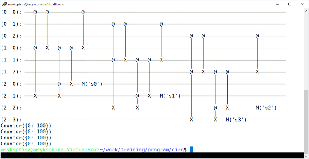
ちなみに、3ビットの加算器だと以下のようになる。まだテストしてないけど。

f:id:msyksphinz:20180923015903p:plain
図. 3ビットの量子加算回路